Using IESRE Two-Channel Reflectometers
David R. Brooks
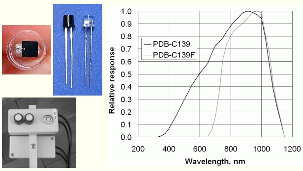
IESRE two-channel reflectometers use a broadband silicon photodector, PDB-C139, and an identical photodetector mounted in a housing which blocks
light from the visible part of the spectrum, PDB-C139F.* Although for brevity I identify these components as VIS and IR,
more specifically, the
VIS device responds to light from the visible and near-IR part of the spectrum and the IR device responds only to light in the near-IR.
As a result, you can't actually separate the broadband and near-IR signals. It is possible, however, to install a lowpass filter over the
VIS device to block the near-IR response. If you are interested in this, please contact me at IESRE.
For use as a reflectometer, you need two of these devices, one pointing up and one pointing down. The upward VIS channel can be calibrated against
a reference pyranometer in
units of watts/m2, but the IR channel cannot (at least not easily).
You don't need an absolute radiometric calibration for reflectance measurements,
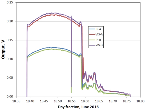
but you do need to calibrate the two units against each other. Mount them side by side pointing up on a clear day and record the outputs for at least several
hours around solar noon. Suppose you label the units A and B. Graph the outputs and find the value such that when you multiply the output of B times that
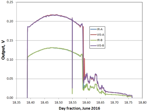
value, its output agrees with A. For the two units shown below, the lefthand figure shows the raw data and the righthand figure
shows the VIS output or the B unit multiplied by 0.975 and the IR output by 1.040.
Suppose A points up and B points down. Then, given a calibration constant C relating the two outputs for one of the two channels,
the reflectance for that channel is:
reflectance = (VB*C)/VA
For most surfaces, you should expect the broadband reflectance to be different from the near-IR reflectance. Reflectance will also vary with
sun elevation and
sky conditions, and hence will vary during a day even under uniform sky and surface conditions. You may be able to use this device to track the health of
uniform vegetation such as mowed grass, especially as a function of rainfall and soil moisture.
The larger and more homogeneous the surface
under and surrounding these instruments, the better your results will characterize that surface.
 |  |
Mount the upward pointing detectors above or right next to the downward pointing detectors,
often somewhere around 1-2 m above the ground.
Use a supporting structure such as a camera tripod and mount the detectors at the end
of a lightweight (aluminum?) angle, c-channel, or square tube extrusion that is as long as practical,
to keep the supporting structure as far away as practical from the view directly under the
downward pointing detectors. (In the photo above, the detectors are fastened to 1/2" aluminum square tubing.) You may have to weight the tripod
to keep it from tipping over. In the northern hemisphere,
the supporting structure should be to the north of the instruments so
shadows from the supporting structure are never directly below the downward pointing instrument.
At IESRE, we are currently using UX120-006M four-channel USB dataloggers from
Onset Computer Corporation to
record reflectance data. The UX120 units provide 16-bit A/D resolution. The previous 12-bit version of these loggers, U12-006,will work, but
their resolution may be inadequate for surfaces with low reflectance. These loggers are rated for indoor use only, but IESRE has found
that they can be used
outdoors in protected environments where moisture will not condense on them.
* The PDB-C139F apparently is no longer in production, although as of summer 2016 it was still available through DigiKey.com, for example.