Note that the op-amp lettering is upside down in this view, but it is mounted correctly on the board.
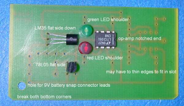
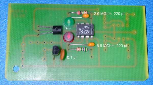
The resistor values may be different. The capacitors, especially the 220 pf capacitors, may look different from the photo.
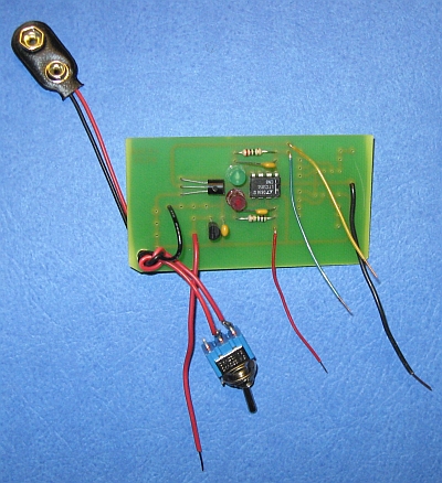
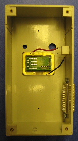
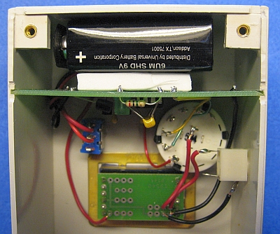
The yellow wire is for the temperature sensor.
- Mount 3.5mm jack as shown.
- Mount db25 connector as shown. Your kit may include #6 sheet metal screws rather than machine screws and nuts.
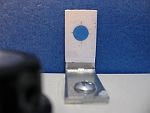
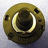
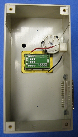
- Mount panel meter, oriented as shown. On some kits, one corner of the retaining clip may be snipped off, as shown here.
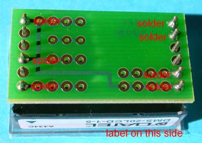
- Solder red and black wires to 3.5mm jack as shown.
- Mount the rotary switch. Several versions of these switches have been used in kits. Also, with the current version of the kit, the order of the T-green-red channels is reversed from what is shown in these photos. The pins to be used for the three outputs should be marked on the switch. If not, the temperature output (use the yellow wire) should be "on" when the rotary switch as viewed from the top is rotated all the way counterclockwise. (Check it with a multimeter set to measure resistance connected between the pin and the center and one of the pins around the outside.) The pin to the right of that, viewing the switch from the bottom (pin end) is for the green channel and the pin to the right of that is for the red channel.
- When you insert the rotary switch, make sure it is oriented propertly so that the knob points to the proper channel. To check the position of the switch, attach the knob to the shaft, with the screw against the flat on the shaft. Rotate the switch all the way clockwise and then rotate it to the left by one position. When the rotary switch is properly oriented, the knob pointer should point to the "grn" position on the label.
- Slide the pc board into the case slots.
- Remove the hardware from the on/off switch. Discard the indexing washer. Orient the switch as shown, with the empty terminal away from the pc board. Attach with lock washer and nut.
- Solder a red wire to the rotary switch as shown.
- Solder the red, green, and yellow wires to the switch poles as shown.
- Solder the red wire from the rotary switch and 3.5mm jack, and the remaining wires from the main pc to the panel meter pc board as shown.
- Make sure the on/off switch is in the "off" position. Attach the 9V battery to its clip and insert it behind a piece of foam insulation as shown.
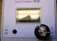
- Test the operation of the instrument. The "T" setting should be the air temperature in degrees Celsius, divided by 100 (for example, 20°C - 0.200V. The red and green channels should read just a few millivolts -- typically 0.003V or 0.004V.
- Clean the surfaces of the LED detectors with a paper towel and make sure there is no dust or debris remaining in the case.
- Fasten the case cover with four screws.
- Mount L-brackets with sheet metal screws as shown. Attach a piece of sticky-backed paper to the front of the rear L-bracket. After the instrument is aligned, the L-brackets should be secured in place with a little super glue around the edges.
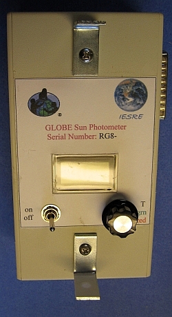
On a day with an unobstructed view of the sun, turn the sun photometer on use the rotary switch to select the red or green channel. Point the sun photometer toward the sun so that a circle of sunlight shining through the front L-bracket falls on the paper face on the rear bracket. Move the instrument around a little, up and down and side to side, and observe where the panel meter signal is the highest. Hold that position and use a sharp pencil to mark a small dot in the center of the circle of light. Select the other channel and repeat. The dots should be in almost exactly the same place.
With a pencil, draw a light cross through the dot (or between two nearly coincident dots). Center a small colored adhesive dot over the cross and press it in place. Gently erase the pencil marks. Finally, wrap a piece of clear tape around the rear bracket to hold the paper and dot in place. When the alignment is completed, put a little super glue along the edges of the L-brackets where they are attached to the case to make sure they do not move.
Your instrument is now aligned and when you make a measurement, you should always center the circle of sunlight on this colored dot. Note that your instrument must be calibrated against a reliable standard before measurements can be used to calculate aerosol optical thickness. Contact IESRE for details.
It is possible that the gain on one or both channels will be too high, depending on the output from the LED detector. If the digital panel meter reads just "1" when the sun photometer is pointed at the sun on a clear summer day near noon, then the gain is too high. The way to fix this is to replace the gain resistors with smaller values. It may be possible to solder an additional resistor in parallel with the existing resistor — this will lower the gain. The resistors can also be removed (carefully!) and replaced. Your kit may include some extra resistors.