Measuring Sunlight at Earth's Surface: Build Your Own Pyranometer
David Brooks, PhD
Institute for Earth Science Research and Education
February, 2007
Introduction
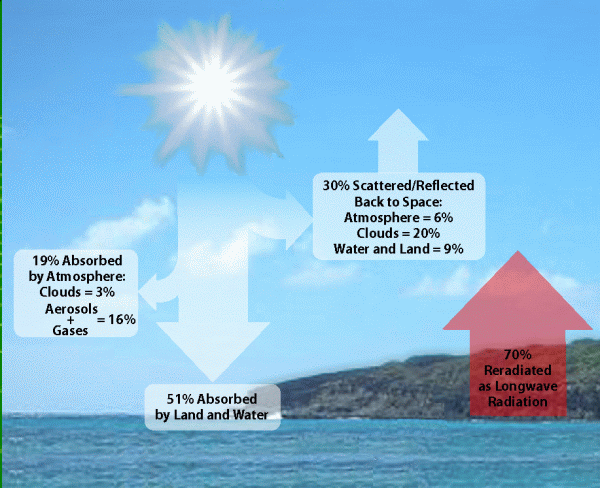 |
Figure 1. How solar radiation interacts with the Earth/atmosphere system
(graphic by Vivek Dwivedi, NASA Goddard Space Flight Center). |
The amount of sunlight reaching Earth's surface is a fundamental quantity for Earth and atmospheric science.
After all, sunlight is the "fuel" that drives the Earth/atmosphere system "engine."
Ultimately, the energy from our sun is responsible for producing and maintaining the conditions required for supporting life as we understand it on our home planet.
The interaction between sunlight and the Earth/atmosphere system are illustrated in Figure 1. At Earth's distance from the sun, an average of about 1370 W/m2
of power reaches the top of the Earth/atmosphere system. About 30% is reflected back to space, mostly by clouds. About 70% is absorbed by Earth's surface and
atmosphere and is then re-radiated in the form of thermal radiation. This interaction keeps the Earth in radiative balance, as required by basic physical laws, and
maintains the Earth's average surface temperature at about 16°C.
The amount of sunlight reaching a horizontal surface at Earth's surface is called insolation, measured
in units of watts per square meter (W/m2).
Insolation (power), or insolation accumulated over some amount of time (energy),
is affected by several factors, including time of day, time of year, latitude,
cloud cover, moisture in the air, and air quality. Although humans obviously have no
control over the purely geometric and temporal factors, there is evidence that
decreasing air quality and changing weather patterns, which are influenced by human
activity, are reducing average insolation in some parts of the world.
Around midday on a summer day in temperate climates, roughly 1 kW/m2 of power reaches Earth's surface. This is a lot of power, even when the available energy is averaged over a day! If this source could be utilized efficiently and stored, the sun could provide essentially limitless renewable, non-polluting, and geographically dispersed energy. However, the dream of harnessing this ultimate source of energy independence has yet to be realized.
You might think that such an important quantity as insolation would have high priority
for ongoing measurements by scientists. However, this is not true. Although there are
atmospheric research programs that include insolation measurements, the last program to
provide nationwide insolation data ended in 1990. In 1992, the U.S.
National Renewable Energy Laboratory (NREL) published the National Solar
Radiation Data Base [NSRDB, 1992], which provides historical insolation data for
several hundred locations in the U.S. However, more than 90% of these data are based on
models of solar radiation, not on actual measurements. Even under "clear sky" conditions,
many assumptions about the state of the atmosphere are required in order to use these models. Under real conditions, the models also depend on statistical analysis of meteorological conditions, especially cloud cover. So, although the NSRDB can tell you a lot about climatological average insolation at a particular site, it has little to say about actual conditions at any given time and place.
Even though the NSRDB is an extremely valuable tool, especially for assessing local
conditions for solar power installations, many of the scientifically interesting
questions that could be answered with a nationwide network of highly accurate insolation
measurements, such as whether reductions in insolation due to deteriorating air
quality are occurring, are not being addressed.
Instruments used to measure insolation are called pyranometers (from the Greek "pyr"
(fire) and "ano" (sky). Ideally, pyranometers should measure all the radiation from the
sun, across the entire electromagnetic spectrum (broadband radiation). Pyranometers
based on thermopile detectors (collections of thermocouples embedded in special
materials) closely approach this ideal. However, such instruments cost several thousand
dollars. Much less expensive pyranometers – what might be called "surrogate"
pyranometers – use miniature silicon solar cell detectors. Commercial versions of these instruments still cost
from a little less than $200 to several hundred dollars.
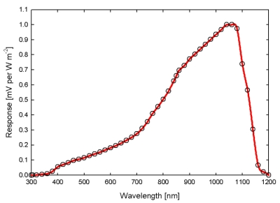 |
Figure 2. Spectral response of a typical silicon solar cell
pyranometer (courtesy of Apogee Instruments, Inc.) |
The downside of so solar cell-based pyranometers is that their response to solar
radiation is strongly peaked in the near infrared and does not extend across the entire
solar spectrum.
The graph at the right, used by permission from Apogee Instruments, Inc., shows the response
of their solar cell-based PYR pyranometer as a function of wavelength. Light visible to
humans falls in the range
from 400 to 700 nanometers. The near-IR peak is near a strong atmospheric water vapor
absorption band. So, these devices are sensitive to changes in water vapor as well as
sunlight.
Despite their shortcomings, solar-cell based pyranometers are widely used for
meteorological, environmental, and agricultural monitoring, and their performance
relative to thermopile-based pyranometers has been studied extensively. Although they
are not suitable for producing stable and highly reliable research-quality data required
for detecting small long-term changes in insolation, data from simple solar cell
pyranometers are still very interesting. They can be used to characterize the potential
of sites to produce solar power and to demonstrate seasonal effects on available solar
energy. Pyranometer data recorded at intervals of a minute or so provide a record of
cloud cover during the day and it has been shown in peer-reviewed scientific
literature [Duchon and O'Malley, 1999] that it is possible to use pyranometer data to classify cloud amounts and
types even when individual measurements of insolation are not highly accurate. It
follows that such data can also be used to track long-term changes in cloud amount and
type – an extremely important indicator of climate change.
Build Your Own Silicon Solar-Cell Based Pyranometer
Solar cell-based pyranometers are conceptually very simple, and it is possible to build them for only a few dollars. However, they require careful design based on an
understanding of the underlying physical principles. As with all such instruments, regardless of their cost, stability and calibration are always the overriding considerations.
For deploying a network of inexpensive pyranometers, one approach is to purchase a single commercial instrument and use it as a calibration source for all the others.
The quality (and cost) of this reference instrument depends on available resources and the ultimate goal of the pyranometer network.
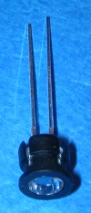
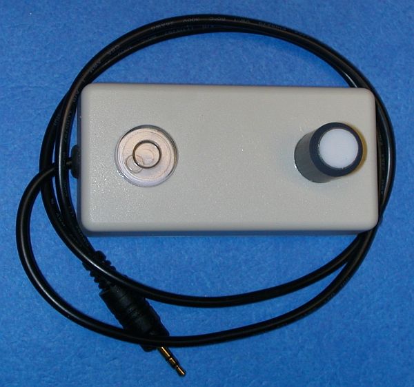
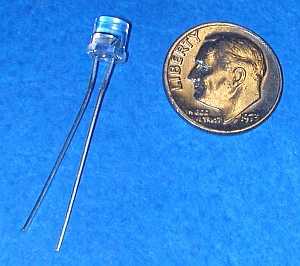 Solar cell pyranometers are built around a silicon photodetector that produces a
small current proportional to the amount of sunlight incident on the detector. The
detector shown here measures 2 mm × 2mm and is housed in a clear epoxy T 1-3/4 case (the same as
the larger of the two standard LED sizes).
If you expose these photodetectors to sunlight and measure the voltage, they will produce
about 0.5 V even in very dim light. However, this is the “open circuit” voltage for
which only a very small number of electrons are flowing (as required for your voltmeter
to make a measurement). This output is not proportional to the amount of sunlight
falling on the detector. What you need to measure is not this open circuit voltage, but
a flow of electrons, which is proportional to the sunlight falling
on the detector. Although it is possible to measure this current directly, it is much
easier to force the detector to do "work" across a load resistor, which will produce
a usable voltage signal that is proportional to the current, following Ohm’s law:
voltage equals current times resistance, V=IR. With a resistance of about
500 ohms, such a device can be expected to produce about 0.1-0.2 V in full sunlight. There
is a trade-off between the desire to increase the output voltage
(by increasing the resistance) and the need to make sure that the pyranometer output remains linearly proportional to the incident sunlight.
(More information about operating and design principles for solar cell-based pyranometers can be found online in Brooks [2006].)
There is one other important design consideration for even the simplest pyranometer.
Ideally, pyranometer detectors should respond to direct sunlight in proportion
to the cosine of the zenith angle of the sun. When the sun is directly overhead,
define the "normalized" response as 1. As the zenith angle increases, the
normalized detector response to direct sunlight should decrease as the cosine of the zenith angle.
Real detectors do not have perfect cosine response. To improve their response,
some kind of sunlight diffuser can be placed over the detector. Teflon®
is often used because it has good spectral transmission properties, is very stable,
and is relatively unaffected by long-term exposure to sunlight.
Construction details for a pyranometer, including a parts list, are given below. Although it is true that the
pyranometers described here are very inexpensive compared to commercial instruments,
buying parts and tools to build just one or two units "from scratch" will
greatly increase the per-unit cost. The holder for the silicon photodetector and its Teflon® diffusing disk must be
machined to very tight tolerances in order to hold the diffuser securely in place. This is virtually impossible to do without access to a
small machine lathe. A complete kit of parts is available from the
Institute for Earth Science Research and Education
for $30, including
shipping in the U.S. This is a much more
cost-effective approach unless you are planning to build several pyranometers and either
already have the equipment you will need or are prepared to make the necessary up-front
investment. With the parts kit, this is an easy construction project that requires
only two solder connections. However, students need to have competent adult supervision for
any project that involves anything as hot as a soldering iron!
Solar cell pyranometers are built around a silicon photodetector that produces a
small current proportional to the amount of sunlight incident on the detector. The
detector shown here measures 2 mm × 2mm and is housed in a clear epoxy T 1-3/4 case (the same as
the larger of the two standard LED sizes).
If you expose these photodetectors to sunlight and measure the voltage, they will produce
about 0.5 V even in very dim light. However, this is the “open circuit” voltage for
which only a very small number of electrons are flowing (as required for your voltmeter
to make a measurement). This output is not proportional to the amount of sunlight
falling on the detector. What you need to measure is not this open circuit voltage, but
a flow of electrons, which is proportional to the sunlight falling
on the detector. Although it is possible to measure this current directly, it is much
easier to force the detector to do "work" across a load resistor, which will produce
a usable voltage signal that is proportional to the current, following Ohm’s law:
voltage equals current times resistance, V=IR. With a resistance of about
500 ohms, such a device can be expected to produce about 0.1-0.2 V in full sunlight. There
is a trade-off between the desire to increase the output voltage
(by increasing the resistance) and the need to make sure that the pyranometer output remains linearly proportional to the incident sunlight.
(More information about operating and design principles for solar cell-based pyranometers can be found online in Brooks [2006].)
There is one other important design consideration for even the simplest pyranometer.
Ideally, pyranometer detectors should respond to direct sunlight in proportion
to the cosine of the zenith angle of the sun. When the sun is directly overhead,
define the "normalized" response as 1. As the zenith angle increases, the
normalized detector response to direct sunlight should decrease as the cosine of the zenith angle.
Real detectors do not have perfect cosine response. To improve their response,
some kind of sunlight diffuser can be placed over the detector. Teflon®
is often used because it has good spectral transmission properties, is very stable,
and is relatively unaffected by long-term exposure to sunlight.
Construction details for a pyranometer, including a parts list, are given below. Although it is true that the
pyranometers described here are very inexpensive compared to commercial instruments,
buying parts and tools to build just one or two units "from scratch" will
greatly increase the per-unit cost. The holder for the silicon photodetector and its Teflon® diffusing disk must be
machined to very tight tolerances in order to hold the diffuser securely in place. This is virtually impossible to do without access to a
small machine lathe. A complete kit of parts is available from the
Institute for Earth Science Research and Education
for $30, including
shipping in the U.S. This is a much more
cost-effective approach unless you are planning to build several pyranometers and either
already have the equipment you will need or are prepared to make the necessary up-front
investment. With the parts kit, this is an easy construction project that requires
only two solder connections. However, students need to have competent adult supervision for
any project that involves anything as hot as a soldering iron!
Calibrating Your Pyranometer
Once you have built and tested your pyranometer, how do you convert the voltage
output into insolation units of W/m2? This is not an easy question to
answer,
regardless of whether your pyranometer costs $20 or $2000! Calibration of instruments
that measure radiation is an ongoing challenge and there are many scientists who
have devoted
their professional careers to understanding and maintaining absolute radiometric
standards. There are two basic choices for this pyranometer:
First, you can calibrate a pyranometer under clear sky conditions by using a so-called
radiative transfer model of solar transmission through the atmosphere.
This is a somewhat circular approach to calibrating instruments that are intended to be
very accurate, because it assumes knowledge of just those characteristics of the
atmosphere (water vapor and aerosols, for example) that affect the
amount of energy being transmitted to Earth's surface. However, for the pyranometers
described here, this approach will yield a reasonable approximate calibration.
Second, you can calibrate a pyranometer against a reference instrument whose calibration
you trust. This approach is practical, but also has some limitations. Very expensive
"world standard" pyranometers are calibrated essentially theoretically, based on
underlying physical principles and detailed radiative transfer models using coincident
measurements of atmospheric properties, based on the assumption that their detectors
respond to the entire total solar spectrum with a carefully measured cosine response to
direct sunlight. They are typically maintained at high-elevation observatories where
atmospheric interference is less of a problem and more easily quantified.
These very valuable absolute reference instruments are then used to calibrate other
research instruments.
This is a much too rigorous (and
expensive) process for a "homemade" pyranometer. A reasonable approach is to
calibrate your pyranometer against a similar commercial pyranometer such as the Apogee
SP or the Kipp & Zonen SP-Lite. These commercial instruments also use a small silicon
solar cell photodetector and therefore have a similar spectral response to your
pyranometer. Their cosine response is better, but this is a
relatively minor consideration if you are interested in total daily insolation, for
example, rather than minute-by-minute comparisons. These commercial instruments are considerably more
expensive than the instrument described here! The SP pyranometer costs
about $170 (summer 2011) plus another $30 for an optional leveling fixture and the SP-Lite 2 costs a little over $400 (with a built-in bubble level).
The Apogee's output is high enough to record with
12-bit 2.5V USB loggers from Onset Computer Corporation, but the Kipp & Zonen output is considerably
lower and requires a much more expensive higher-resolution data logger. NOTE: In the past, some of our
Apogee pyranometers have shown very large and unpredictable changes in output when
used under typical conditions for just a few months. We have not seen these problems with newer units and we are one again comfortable with
recommending them as calibration sources for these pyranometers.
This approach makes sense if you would like to build a network of identical pyranometers.
Then, the commercial instrument will serve as a reference standard against which to calibrate
all the
other instruments in the network. For just one instrument, it may be worth paying someone
to provide a calibration. Contact the
Institute for Earth Science Research and Education
for more information.
It's important to understand that the performance of even expensive pyranometers change with
time, so calibration is an ongoing process and not just a one-time event. A typical
manufacturer's recommendation is to recalibrate pyranometers every two years. This is a
recommendation that, unfortunately, is rarely followed even for research-quality
instruments!
Using Your Pyranometer
In order to use your pyranometer, you need to record its output. Single measurements of
insolation, even at several times throughout the day, are not really
very useful except for demonstration purposes. I record insolation data at 1-minute
intervals using a standalone data logger from Onset Computer Corporation –
either the U12-006, with four external voltage inputs, or the U12-013, with two external
voltage inputs and internal temperature and relative humidity sensors.
These loggers have a USB interface and require proprietary software ("HOBOware Lite"
is adequate) for communicating with a computer. The data are stored in a proprietary
binary format, but can be saved as a text file that can be imported into Excel and
other spreadsheets.
The U-series loggers record a DC voltage input from 0-2.5 V at 12-bit resolution. This
gives a signal resolution of 2.5/4095 = 0.6 mV. This is adequate resolution even though
the pyranometer signal will never exceed a few tenths of a volt. Because of this
relatively low output, lower resolution loggers (8- or 10-bit, including older Onset
Computer Corporation "HOBO" loggers with serial port connectors) are inadequate for this
instrument.
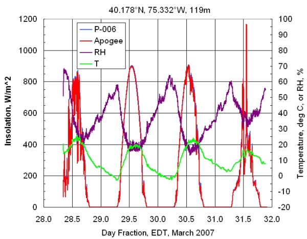 The graph here shows several days of insolation recorded at my house in late March, 2007, with a U12-013 logger. The two external voltage signals are from a calibrated Apogee pyranometer and a
pyranometer identical to the one described in this document. The maximum output voltage
from P-006, around 1:00 pm on March 31, was about 0.29 V. A calibration constant of
4800 (W/m2)/V applied to P-006 produces excellent agreement between these two
instruments. (The corresponding calibration constant provided for the Apogee instrument is 4030 (W/m2)/V.)
The big question is, "Are these data correct?" First of all, it should be noted that my
observing site is surrounded by trees and is less than 20 m from our two-story house,
so direct sunlight on the pyranometer is blocked especially in the early morning and some
of the diffuse sky radiation never reaches the pyranometer. However, around solar
noon, the total diffuse radiation from the entire sky is less than 15% of the total
insolation, so the reduction in insolation due to the characteristics of my site are
very small around solar noon. On a clear day such as March 29, it is reasonable to test
the results against a radiative transfer model.
The well known and widely used "Bird Model" [Bird and Hulstrom, 1981] yields an insolation at local solar noon of about 848 W/m2 on March 29, 2007, using average values for aerosols, water vapor,
and ozone. The observed calibrated value is around 900 W/m2, about 6% higher. Insolation is particularly sensitive to water vapor and this was a very dry day. Data from NOAA indicate
that the total precipitable water vapor was only about 0.2 cm H2O rather than
the assumed default value of 1.5. This single change, which is very important because of
the
previously noted sensitivity of solar cell detectors to water vapor, raises the modeled maximum solar noon insolation to almost
900 W/m2. Dry days often have low aerosol optical thickness, too, and lowering
the default values by only a little will raise the maximum to over 900 W/m2.
The graph here shows several days of insolation recorded at my house in late March, 2007, with a U12-013 logger. The two external voltage signals are from a calibrated Apogee pyranometer and a
pyranometer identical to the one described in this document. The maximum output voltage
from P-006, around 1:00 pm on March 31, was about 0.29 V. A calibration constant of
4800 (W/m2)/V applied to P-006 produces excellent agreement between these two
instruments. (The corresponding calibration constant provided for the Apogee instrument is 4030 (W/m2)/V.)
The big question is, "Are these data correct?" First of all, it should be noted that my
observing site is surrounded by trees and is less than 20 m from our two-story house,
so direct sunlight on the pyranometer is blocked especially in the early morning and some
of the diffuse sky radiation never reaches the pyranometer. However, around solar
noon, the total diffuse radiation from the entire sky is less than 15% of the total
insolation, so the reduction in insolation due to the characteristics of my site are
very small around solar noon. On a clear day such as March 29, it is reasonable to test
the results against a radiative transfer model.
The well known and widely used "Bird Model" [Bird and Hulstrom, 1981] yields an insolation at local solar noon of about 848 W/m2 on March 29, 2007, using average values for aerosols, water vapor,
and ozone. The observed calibrated value is around 900 W/m2, about 6% higher. Insolation is particularly sensitive to water vapor and this was a very dry day. Data from NOAA indicate
that the total precipitable water vapor was only about 0.2 cm H2O rather than
the assumed default value of 1.5. This single change, which is very important because of
the
previously noted sensitivity of solar cell detectors to water vapor, raises the modeled maximum solar noon insolation to almost
900 W/m2. Dry days often have low aerosol optical thickness, too, and lowering
the default values by only a little will raise the maximum to over 900 W/m2.
So, the Bird model yields values that are consistent with what is recorded by
the Apogee pyranometer, but the default values need to be adjusted to give really good agreement.
A reasonable question is, "Does the Bird model prove that the Apogee pyranometer data
are correct, or the other way around?" Assuming that the Apogee pyranometer has been
calibrated against a high-quality thermopile pyranometer, the latter is probably a better answer
than the former.
However, it is difficult in any case to assess the absolute radiometric accuracy of either
the measurements
or the model,
because of the difficulty of determining what the "correct" value actually is. It is
perhaps reasonable to conclude that after your pyranometer is calibrated against a reliable
standard it will give daily summed
insolation (but not necessarily instantaneous values) accurate to within
+/-10% of their actual values.
It may be unexpected to see output voltages such as observed on March 31 that are greater than the maximum value for a clear sky day.
However, this is quite common (even more common than is evident from this particular data
set), and results from the reflection of sunlight off the sides of clouds. For many more
examples of pyranometer data recorded at one-minute intervals, see these
insolation data from students.
References
Richard E. Bird and Roland L. Hulstrom
A Simplified Clear Sky Model for Direct and Diffuse Insolation on Horizontal Surfaces,
SERI/TR-642-761, Solar Energy Research Institute, Golden, Colorado, USA, February 1981,
online at
http://rredc.nrel.gov/solar/pubs/PDFs/TR-642-761.pdf
Brooks, David R., Monitoring Solar Radiation and Its Transmission Through the Atmosphere, 2006,
online at
http://www.pages.drexel.edu/~brooksdr/DRB_web_page/papers/UsingTheSun/using.htm
Duchon, Claude E., and Mark S. O'Malley, Estimating Cloud Type from Pyranometer Observations, Journal of Applied Meteorology, 38, pp 132-141, 1999.
Finsterle, Wolfgang, Isabelle Rüedi, and Silvio Koller,
The World Radiometric Reference and its Quality System, ISO/IEC 17025,
online at
www.knmi.nl/samenw/geoss/wmo/TECO2005/ppt/3/3(15)teco2005-2.ppt
National Solar Radiation Data Base User's Manual (1961-1990), 1992,
online at
http://rredc.nrel.gov/solar/pubs/NSRDB/NSRDB_index.html
Construction Details
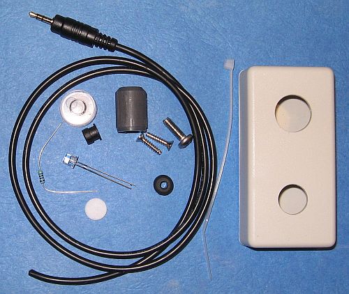 These parts are provided with the kit and do not need to be purchased separately. The extra information is given if you
wish to build your pyranometer from scratch. Parts availability and prices are subject to change and are beyond the control
of IESRE!
These parts are provided with the kit and do not need to be purchased separately. The extra information is given if you
wish to build your pyranometer from scratch. Parts availability and prices are subject to change and are beyond the control
of IESRE!
- ABS plastic case, 3.15" x 1.57" x 0.8", DigiKey HM380-ND ($2.00/$1.66 1/10 units) or All Electronics Corporation 1551-KGY, ($2.10 each)
- silicon photodetector, DigiKey Corporation PDB-C139-ND, ($3.30/$2.03/$1.80 1/25/100 units)
- 470-Ohm, 1/4-Watt, 1%, metal film resistor, DigiKey Corporation 470XBK-ND, $0.098 each, minimum 5. Note: any value around this size is OK. Metal film resistors are used only because they are less temperature-sensitive than carbon film resistors, not because a specific resistance value is needed.
- T 1-3/4 LED holder, All Electronics HLED-4, 10 for $1.20
- 2.5 mm stereo plug and cable – 5 feet, AC2511, DCables. Cut in half for two input cables for use with Onset Computer Corporation USB logger listed below. Do not substitute a 2.5 mm mono plug with this logger!
- rubber or soft plastic grommet, 1/8" ID with 3/16" panel hole, McMaster-Carr 9600K17, $3.25 per pack of 100
- 1 mm (0.039") thick x 3/8" diameter Teflon® disk (punch from 6"x6" square sheet, McMaster-Carr 8545K12, $3.04)
- small "bullseye" bubble level, McMaster-Carr 2147A61, $2.18 each. (The optional mounting flange is not needed.)
- 3/4"-long piece of 1/4" (nominal inside diameter) thick-walled gray PVC plumbing pipe, ~$2.00/ft from a plumbing supply store. Note that this component is machined for the detector and
diffuser disk, and for mounting on the case, an operation for which there is no practical alternative to a small machine lathe if you are building your pyranometer from scratch.
- small cable tie
These are needed to assemble the kit.
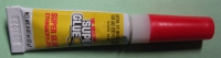 small tube of cyanoacrylate liquid glue ("superglue")
NOTE: The appropriate superglue for this project is a thin liquid. Some versions of this kind of
glue should be avoided because they are more viscous and are difficult to apply in very small amounts, as is
required for the delicate job of cementing in place the Teflon diffuser, as described below in Step 15.
small tube of cyanoacrylate liquid glue ("superglue")
NOTE: The appropriate superglue for this project is a thin liquid. Some versions of this kind of
glue should be avoided because they are more viscous and are difficult to apply in very small amounts, as is
required for the delicate job of cementing in place the Teflon diffuser, as described below in Step 15.
- a small soldering iron (15-40 watt) and 1/32" (preferred) or 1/16" diameter resin core solder.
- miscellaneous tools – pliers, wire cutters, etc.
The following tools are required to build a pyranometer "from scratch." These tools are not needed to build a pyranometer from a parts kit.
- 3/8" hole punch (also called an "arch punch"), McMaster-Carr 9611K14, $20.31
- 1/4" drill
- 1/2" and 5/8" diameter drills. The best drills for holes this large in thin plastic are Forstner bits, available from woodworkers' suppliers. Spade bits will also work if they are sharp and used very carefully. Use a drill press, not a handheld drill, with either of these types of drills. Use safety goggles, gloves to protect your hands, and be careful to secure the workpiece before drilling!
Data recording:
12-bit USB datalogger, Onset Computer Corporation U12-006 (4xDC volts), $95, or U12-013 (T, RH, 2xDC volts), $119. These are general-purpose loggers that can be used with a variety of input sensors for a wide range of measurements. Note: 8- or 10-bit loggers do not have enough resolution for use with this pyranometer.
HOBOware Lite Software, Onset Computer Corporation, $39. (This proprietary software is required for the U12 loggers.)
URLs for vendors:
(DigiKey) www.digikey.com
(DCables) www.dcables.net
(All Electronics) www.allelectronics.com
(Onset Computer Corporation) www.1800loggers.com
(McMaster-Carr) www.mcmastercarr.com
(Woodworker Supply, for Forstner bits) www.woodworker.com
Assembly Instructions
Read completely through these instructions before starting the actual construction. Make sure you have the tools you will need.
What is referred to here as the "top" of the pyranometer is the "bottom" of the case. The removable lid will be the "bottom" of the pyranometer.
IMPORTANT NOTES — READ BEFORE STARTING CONSTRUCTION:
 There a few problems that are commonly encountered in constructing this instrument. When you superglue the LED holder to the photodiode, do NOT let superglue run onto the
surface of the photodiode. Although you can wipe away superglue for a few minutes after it is applied, you cannot completely remove it from the surface
of the photodetector and this will change the performance of the photodetector. After the glue is hardened, it is impossible to remove it from a plastic surface.
Getting superglue on the surface of the photodetector will ruin the detector assembly beyond repair!
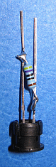
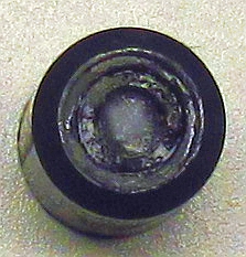
The image here shows a housing with a LOT of glue where it shouldn't be! This instrument will function, but it will not give
reliable results. Superglue has covered the surface of the photodetector. It is pointless to try to calibrate this instrument
because the glue will dramatically lower the output of the photodetector and that output will change drastically over time
as the glue "ages" and becomes more opaque – this assembly cannot be salvaged!
There a few problems that are commonly encountered in constructing this instrument. When you superglue the LED holder to the photodiode, do NOT let superglue run onto the
surface of the photodiode. Although you can wipe away superglue for a few minutes after it is applied, you cannot completely remove it from the surface
of the photodetector and this will change the performance of the photodetector. After the glue is hardened, it is impossible to remove it from a plastic surface.
Getting superglue on the surface of the photodetector will ruin the detector assembly beyond repair!
The image here shows a housing with a LOT of glue where it shouldn't be! This instrument will function, but it will not give
reliable results. Superglue has covered the surface of the photodetector. It is pointless to try to calibrate this instrument
because the glue will dramatically lower the output of the photodetector and that output will change drastically over time
as the glue "ages" and becomes more opaque – this assembly cannot be salvaged!
When you seat the LED holder and photodetector assembly in the housing, make sure that assembly is firmly in place just below the surface of the machined recess where
the Teflon diffuser goes. Do not get superglue into this recess, as it is virtually impossible to remove later and this will prevent the Teflon diffuser from
snapping into place in the recess.
When you seat the Teflon diffuser in its recess, use only a TINY amount of superglue around the recess. If you use too much glue it will spread under
the diffuser and onto the surface of the photodetector. You will not be able to see this happening, but it will degrade the performance of your pyranometer and may
cause the calibration of your instrument to change with time as the dry glue changes properties after prolonged exposure to heat under the diffuser.
It is worth trying a "dry run" on the Teflon diffuser before you install the LED/photodetector assembly. You can snap the Teflon into its recess and remove it by pushing it
out from the other end of the detector housing (gently!) with a small screwdriver. If the Teflon diffuser is really a hard snap fit in its recess, it may not even be
necessary to apply superglue. As noted elsewhere, the superglue doesn't actually stick to the Teflon and just provides a little mechanical contact that will help to
hold the diffuser in place.
Another common problem is touching and melting the sides of the plastic case with the soldering iron when you solder the cable leads to the photodetector leads.
If you catch this before
the plastic cools and hardens (you should be able to smell it!), you might be able to "reshape" the melted part of the case edges. In any event,
you should trim the melted parts after they harden again so that the lid still
fits tightly — otherwise water will get into the case. If there are gaps where the plastic has melted, you can seal the lid with silicone bathtub caulk
(or similar). In fact, you could do this even if the case hasn't been damaged. After you are sure your instrument is working properly, you should never need to
open the case again.
Finally, make sure that the wires connected to the photodetector leads, and the photodetector leads themselves, are spaced well apart. Make sure that the
"third wire" that you have clipped off (the one connected to the middle ring of the 2.5mm stereo plug) will not touch either of the other two wires. Sometimes,
in damp weather when condensation is possible, wires that are close to each other, even if they're not actually touching, may be "shorted" due to
condensation. This will be an intermittent problem that is hard to test for in advance, so the only real solution is to be careful with the placement of
the wires in the first place.
| Instructions | Construction Photos |
|---|
- Insert the grommet into the hole at end of the case. Use a small blunt object such as a small screwdriver.
Be careful not to cut the grommet.
(The grommet is the soft rubber O-shaped item, not the hard black plastic LED holder for the photodetector.)
- Spread a small amount of superglue around the inside of the larger of the two holes in the top of the case. Insert the bubble level from the inside of the case.
Make sure the bubble level's shoulder seats firmly against the top of the case. Set the case aside, upside down, to let the glue dry for several minutes.
-
Insert the photodetector into the plastic LED holder. The top of the photodetector must be level with the rim of the holder. Use a few small drops of superglue to bond the body of the
photodetector to the holder. Be careful not to get any superglue on the front surface of the photodetector. Set the detector-holder assembly aside to dry. It may take as long as several
hours for the glue to dry completely. Do not continue until the glue is completely dry.
- Wrap the resistor leads around the detector leads, as shown. It doesn't matter which way the leads of the resistor are oriented.
Solder to the leads and trim off the excess resistor leads. Be careful not to overheat the resistor. Make sure that the trimmed leads do not touch the opposite detector lead.
- Once the wire leads are soldered in place, make sure that the exposed wires do not contact each other anywhere.
-
Insert the detector-holder assembly into the housing. The rim of the holder must sit level with or just below the machined recess in the end of the housing. Do a "dry run" first, to
make sure the detector assembly sits level in its recess. Then remove the assembly. Spread a little superglue around the inside of the housing. Be careful not
to get any glue on
the surface of the machined recess. Then insert the detector-holder. Make sure it is sitting level in the housing and set it aside until the glue is completely dry.
Note: In earlier versions of this kit, a slight recess was machined into the housing so the LED/holder assembly would fit inside. In more recent
versions, there may be no recess because the inside diameter of the housing tube is a little larger. For these versions, you must spread glue around the inside of the
housing and then slip the LED holder into the tube. It should sit level in the tube, just barely below the machined recess for the Teflon diffuser. Make sure the
holder doesn't move for a few minutes, to give the superglue a little time to set.
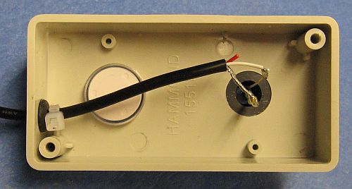
- Insert a few centimeters of the cut end of the plug and cable assembly through the grommet, from the outside to the inside of the case,
where the detector housing will go. If the cable is hard to push, moisten it with a little hand lotion or dish detergent.
Note: In later versions of this kit, the hole through which the cable goes is at the end nearest the detector housing, not the end nearest
the bubble level. This change was made to ensure that the mounting screw on the bottom of the case didn't push on the cable when it was screwed in. For the newer
versions,
less cable will have to be inserted through the grommet. Otherwise, the instructions remain the same.
- Carefully remove about 2 cm of the cable jacket, using a sharp knife. Be careful not to cut into the wires or the copper shield in the cable. It is
OK if you need to push a little more cable through the grommet to do this.
- Twist together all the very fine shield wires. Strip about 0.5 cm of insulation from the white wire. Clip the red wire down near the cable
jacket – it will not be used.NOTE: The color coding of the wires on your cable may be different from
what is shown here. In any case, the wire that connects to the tip of the 2.5mm plug (the white wire
in this photo and in the most recent versions of the kit) must be used and
the wire that connects to the middle ring on the plug (the red wire in this photo) must be cut off.
Use a multimeter to check these connections before you proceed and be sure to use the correct wire!
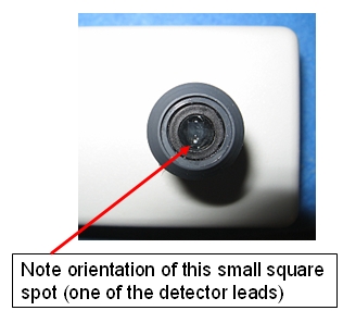
- Spread a little superglue around the shoulder on the bottom of the detector housing. Insert the housing into the remaining hole in the top of the case.
Use a twisting motion to align the housing so that the sides of the square solar cell in the photodetector are aligned parallel and perpendicular to the sides of the case, preferably oriented
as shown.
Make sure the housing is seated firmly in its hole so that the housing is perpendicular to the top of the case. Work quickly, as the glue dries rapidly here.
- One lead of the detector is a little longer than the other. This is the positive ("+") lead.
Crimp the end of the white wire (or whichever color wire you have determined is attached to the tip on the 2.5mm stereo plug)
around the positive photodetector lead and solder
it to the positive lead. Make sure that the entire connection is hot enough so that the solder flows,
but do not apply more heat than needed. Using too little heat may result in a
"cold" connection that will fail some time in the future.
- Crimp the twisted braid around the negative ("-") photodetector lead and solder it.
-
Put a cable tie around the cable and use pliers to pull it tight right next to the grommet on the inside of the case.
- Test the output from your pyranometer by applying voltmeter test leads to the tip and base of the 2.5 mm plug. Because you are no longer measuring the "open circuit" voltage,
this output will be much smaller than your previous measurement. In full sunlight, the output should be a few tenths of a volt.
Note that there should be no voltage applied to the middle ring in the plug. However, a digital voltmeter will typically not read 0 if you test the voltage between the
middle ring and base of the plug.
Instead, it will probably produce "junk" values that are of no concern.
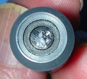
- The final step is to mount the Teflon diffusing disk over the photodetector assembly. This is a critical step that requires a great deal of care! Pick up the disk with a paper towel
or tissue and rub both surfaces gently to remove any dust or debris that might be there.
Apply a very small amount of super glue around the recess in the top of the detector holder. Carefully remove any excess glue with the corner of a paper towel, tissue,
or Q-tip. Be very careful not to get any
glue on the surface of the photodetector. Insert the Teflon disk -- it
should "snap" into place -- and push gently with a paper towel or a small flat piece of soft wood, or push the disk gently on a flat surface. (Try to avoid touching the Teflon with your fingers.
Let the glue dry for a few minutes. Then take the small piece of fine abrasive paper included with the kit and gently abrade the surface of the Teflon with a circular motion, just enough
to remove the "shine" from the disk.
NOTE: Superglue doesn't actually adhere very well to Teflon (hardly anything does!). It adheres to the photodetector housing and, when it dries, it
makes a basically mechanical bond by just "filling in" the tiny voids around the circumference
of the Teflon disk. This should hold the Teflon in place, but it is easy to break this weak bond and then the disk can pop out of its recess. I have had this happen occasionally but, with
reasonable care, it shouldn't be a problem.
- When you are convinced that your pyranometer is working properly, attach the bottom of the case with the screws provided.
Optionally, especially if standing water could collect around the base of the case, you can apply a little silicone caulk (like
bathtub caulk) around the edges of the case and in the screw holes before you fasten the bottom. The machine screw provided is for attaching the pyranometer to a base.
Be careful not to overtighten the screw in its threaded hole in the case lid, as you will strip the threads in the soft plastic of the lid.
- If you are going to use the screw provided for fastening your pyranometer to a mounting bracket,
twist the screw part way into the hole in the cover so it doesn't get lost.
- If you plan to record data from more than one pyranometer at a time with a USB-series data logger from Onset Computer
Corporation, the 2.5mm stereo plug housings on the cables provided may be too large to fit side-by-side in adjacent
channels of the data logger.
If this is the case, pare down opposite sides of the housings with a sharp craft knife.
|
|
|
| Steps 3, 4, and 5 |
 |
| Step 11 |
 |
| Step 13 |
 |
| Completed pyranometer assembly |
|