Solar cells and other photodetectors are current-producing devices; light incident on such devices causes electrons to flow. Even the ubiquitous light emitting diodes (LEDs) can work this way. In a normal application, applying a voltage to an LED (causing a current to flow through it) produces light. However, shining light on an LED will produce a small current. (This is how LED-based sun photometers work.)
It is often required to record the output from photodetectors and store them directly in a computer or in the internal memory of a stand-alone data logger. It is possible to convert the current output to an analog voltage output by forcing the device to do "work" across a load resistor. However, the voltage available in this way, without destroying the linear relationship between current and voltage (which is necessary in order to interpret the output from such devices), is often only a few tens of millivolts, whereas data loggers accept voltage inputs typically in the range from 2.5-10 V.
Connecting a voltage signal that is much smaller than the full-scale range of a data logger won't hurt anything, but it results in a loss of resolution in the analog-to-digital conversion of the voltage for computer storage. As a result, it may be desirable to convert current to an amplified voltage that makes optimum use of the range of the data logger. For example, if a 12-bit data logger accepts an input voltage in the range of 0-5 V, its resolution is approximately 1 mV. This might be OK, but it is more of a problem for lower-resolution data loggers. For example, an 8-bit, 2.5-V logger has a resolution of only about 10 mV, as does a 10-bit, 10-V logger. That is, the smallest change in input voltage that will be recorded is about 10 mV. For an input with a maximum value of 100 mV, this is 10% of the total signal. If the input has a maximum value of 10 V, 10 mV is 0.1% of the total signal.
The solution to this problem is to use an operational amplifier to build what is called a transimpedance amplifier – an amplifier that converts current to a voltage that is proportional to the current. By controlling the gain of such an amplifier, even a very small input current can produce a sizable output voltage. Such a circuit is easy to build.
Op-amp that will work with a single supply voltage
Feedback resistor, value to be chosen based on application
0.1 μf capacitor
Bypass capacitor, value to be chosen based on application
SPST on/off switch
9-V battery clip
9-V battery
Red and black #22 gauge wire (solid may be easier to work with than stranded)
The photos show a transimpedance amplifier assembled on a "breadboard" used for electronic prototyping. The rows of 5 connection points running perpendicular (vertically, in this view) from either side of the center channel are electrically connected, but the points are not connected horizontally. The circuit shown uses a 9-V battery, but any voltage between about 5 and 15 V will work -- the gain of the amplifier is independent of the supply voltage (up to the supply voltage) within these limits.
This circuit uses an LTC1050 op-amp, a high-quality low-noise amplifier that operates from a single power supply. Note the position of the small semicircular notch in one end of the op-amp case; it is on the right side of the op-amp in this image. The 0.1-μf capacitor across the battery supply stabilizes the circuit. This amplifier uses a 10-KOhm feedback resistor. (The color code is brown-black-orange, reading up from the bottom of the resistor in this view. The top band (gold) indicates that it is a 5% tolerance resistor.)
There is a 220-pf capacitor in parallel with the feedback resistor, which controls the gain of the circuit. The purpose of this capacitor is to stabilize the amplifier, especially when the gain is very high. Probably it is not necessary for this circuit, which does not need a very high gain. (In the same configuration, an amplifier using an LED as a current-producing device might require a feedback resistor of 10 MOhm or more.) With the small solar cell shown, this circuit produces almost 6V in hazy, partly cloudy summer sunlight. The voltage output of this circuit is linearly proportional to the current produced by the solar cell, which is necessary in order to be able to convert the voltage output into solar power units with a single calibration constant.
The solar cell's "-" lead is on the right side of the image, connected to the op-amp's pin 2 (the pins are numbered from 1 through 8, starting in the upper righthand corner and proceeding counterclockwise.) Note the small "jumper" wire connecting pins 3 and 4.
For a real application, this circuit can be reproduced on "perf board" that is configured identically to this prototyping board, for example, RadioShack Part #276-170. A very compact version of this amplifier is shown in the third image below. It lacks only the power supply connections, to be made on the right hand edge of the perf board.
The image below shows a two-channel circuit such as is used in IESRE's two-channel sun photometers and two-channel radiometers. The LTC1051 is a two-channel version of the LTC1050, still in an 8-pin DIP case. In this circuit, a PDB-C139 photodiode (the sensor in the clear case, and the same sensor as used in IESRE's pyranometer) is paired with the PDB-C139F photodiode, which responds to light only in the near-infrared. The gain resistor for these devices should be a few thousand ohms to get an output in the 1-2 V range in full sunlight. (The 0.1 μf capacitor across the power supply leads, under the red wire, looks different from the one in previous images, but it has the same capacitance value.) In this layout, the shoulders of both photodiodes (on the "-" lead side) face toward the right.
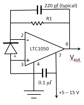
Schematic diagrams for the one- and two-channel transimpedance amplifiers are shown below.
 |
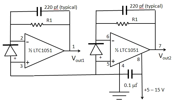 |
| One-channel schematic | Two-channel schematic |