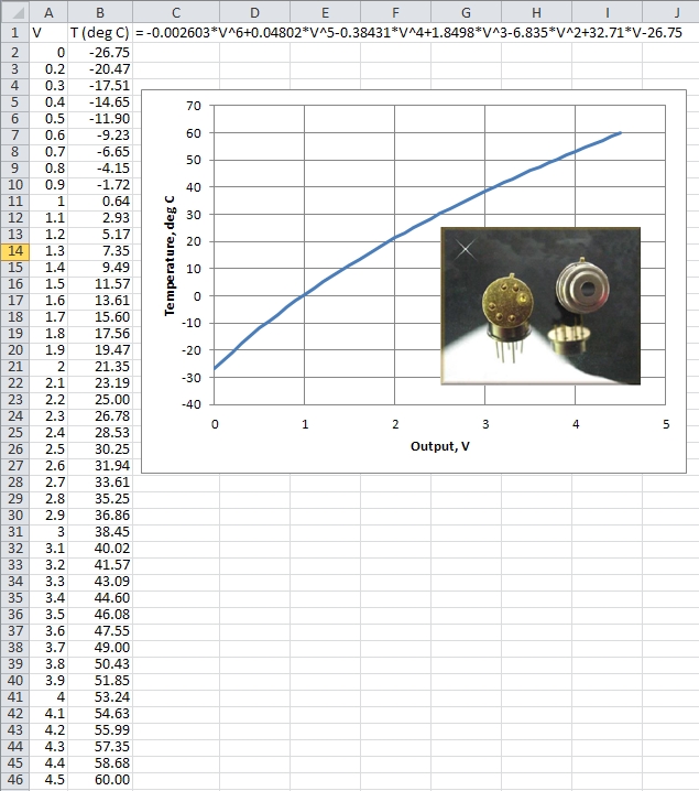
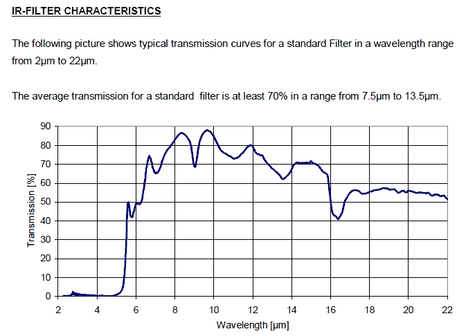
The Excelitas TPS 1T 0134 OAA060 thermopile sensor is a self-contained module with a built-in op amp. (We use the A2TPMI 334 OAA 60 designation in this document because that was the PerkinElmer part number when we purchased them. Since then, PerkinElmer's optoelectronics division has been sold to Excelitas (www.excelitas.com) and online searches will still bring up references to this device under the PerkinElmer name and part number. The TPS sensor is described by Excelitas as a "recent upgrade" to the TPMI sensors. It is possible that specifications for the TPS sensor — and, in particular, the equation for converting voltage to temperature — might be slightly different from the A2TPMI.) These detectors sense thermal radiation, with spectral response as shown in the graph below. The units come in a variety of configurations, including units that are pre-calibrated for converting voltage to temperatures in °C. The AT2PMI 334 OAA060 version produces a voltage output in the range of 0-4.5 V, corresponding to a temperature range from -27°C to 60°C. (Only the most extreme polar regions are likely to lie outside this range!)
A kit of parts for building this instrument is available from IESRE. See this link for details.
| The A2TPMI in this configuration has a full width half height field of view of 60°. | 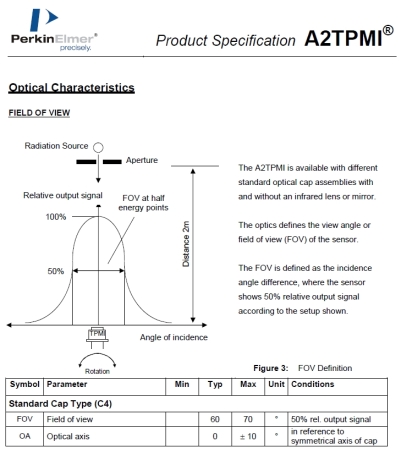 |
It is easy to check out the operation of an A2TPMI with a multimeter. It requires only a regulated +5V power supply, which can easily be provided with an IC voltage regulator (78L05) and a 9-V battery. The circuit doesn't require much power and even a carbon a 9-V battery (sometimes referred to as "heavy duty") widely available at two-for-$1 at dollar stores will last for a couple of days of continuous operation. Because of the chopper-stabilized op amp used in this device, there is a small high-frequency signal on the output, but it should be negligible for this application.
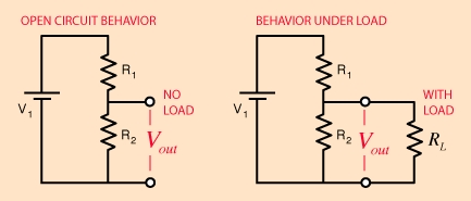
There are some potential problems using this device with a data logger. For most of our projects, we use 12-bit-resolution HOBO U-12 series data loggers. These loggers have an input impedance of only 10 kΩ, but, the A2TPMI requires a minimum resistive load of 50 kΩ. Also, the A2TPMI voltage output exceeds 2.5 V for temperatures above 30°C — a surface temperature value that is often exceeded. The solution is to combine a passive voltage divider with a unit-gain non-inverting amplifier. Such a circuit can provide the A2TPMI with an acceptably high resistive loading. An op-amp-based unit-gain amplifier has a very high input impedance (so that the load on the voltage divider can be neglected) and a very low output impedance. Such a circuit provides an appropriate interface between the AT2PMI and the U-12 logger. If the voltage is divided in half, it will never exceed the 0—2.5 V range of the U-12 logger. This requires two equal resistors whose total value (R1 + R2) is at least 50kΩhm. If high-precision resistors are used, then the output from the unit-gain amplifier is just multiplied by 2 to do the temperature calculation shown above. If only 5% carbon film resistors are available, it is possible to test several samples to find two with very close to the same value. It would also be possible to use a variable resistor, a "trim pot," to adjust the divider so the output from the unit-gain op amp is exactly half the output from the A2TPMI. In any case, units should be calibrated by measuring the output voltage directly from the A2TPMI and the comparing it to the output from the op amp, to determine the precise relationship between the sensor output and the amplified output voltage.
(http://www.onsetcomp.com/support/faq)
(http://hyperphysics.phy-astr.gsu.edu/hbase/electric/voldiv.html)
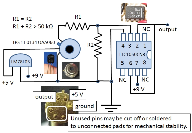
A circuit diagram is shown below. The op amp should be a high-quality low-noise device. We typically use the LTC1050 for these applications, although there are other pin-compatible choices. (The ubiquitous 747 op amp does not qualify as a "low-noise" alternative, even though it is pin-compatible.) Because this is such a low-power circuit, A 78L05 5-V regulator in a TO-092 housing is the appropriate choice. The pins on the A2TPMI are fragile, and it might be a good idea to secure at least one of the unused pins to an unconnected solder pad for mechanical stability. All components in the diagram are as viewed from "above," that is from the component side of a board. Depending on how this unit is housed to protect it from weather, it might be necessary to turn the A2TPMI over and mount it on the opposite side of the board. If you do this, make sure you connect the pins appropriately!
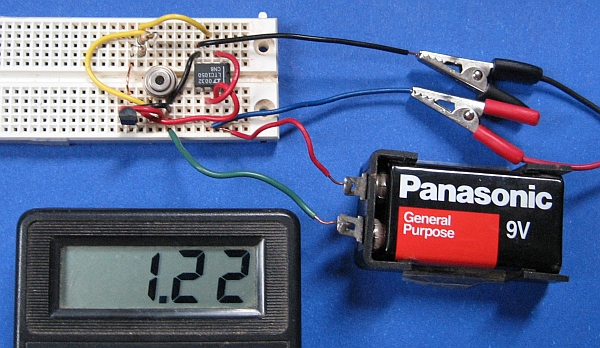
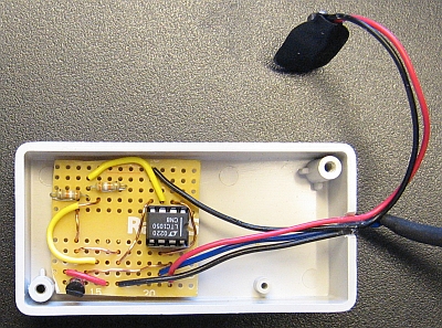
A breadboard version of this circuit built for testing is shown below. A printed circuit board that matches the pin layouts of this breadboard is available from RadioShack,
catalog #276-170. The blue wire is the output from the op amp. Multiplying the displayed value of 1.22 V times 2 and converting to temperature
gives 29.2°C. A Kintrex IRT0421 IR thermometer (with a smaller field of view) pointed up at the same indoor location gave
a temperature of 29.4°C.
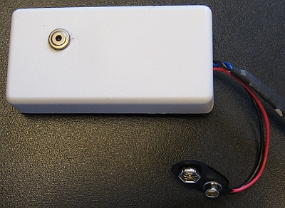
Here is a prototype based on the breadboard circuit. The sensor is mounted on the underside of the board. The op amp is in an 8-pin DIP socket rather than being soldered directly to the board. Why? Because these boards are easily damaged, especially if wires need to be moved and re-soldered, and using a socket ensures that the op amp can be reused if the board is damaged. Because it is relatively fragile and expensive, the A2TPMI sensor should be soldered in place last, after carefully inspecting the rest of the connections.
 |  |
Temperature can be converted to radiated thermal energy E by using the Stefan-Boltzmann equation:
E = εσTK4
where ε is the surface emissivity, a dimensionless quantity with a value between 0 and 1,
σ = 5.670373•10-8W m-2K-4 is the Stefan-Boltzmann constant,
and TK = TC + 273.15 is the conversion from centigrade degrees to absolute temperature in kelvins. Surface emissivity is 1 for an ideal radiator. A
value of 0.95 is often used for natural surfaces.
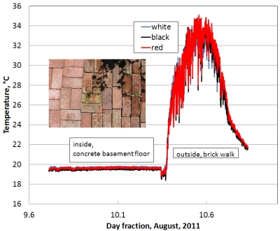
The graph below shows the output from three sensors mounted close together. Overnight, the sensors were inside, pointed down at a concrete basement floor. (Nor surprisingly, the temperature of the concrete floor is essentially constant, so the variability gives some idea of the "noise" in the measurement.) In the morning the sensors were moved outdoors and pointed down at a brick walk next to a flower garden. The agreement among the temperatures from the three sensors is good. This is a very encouraging result, considering that the two 39kΩ 5% carbon film resistors used for the voltage dividers were not pre-matched by value ahead of time and no attempt has yet been made to calculate more precisely the ratio of the full output from the sensors to the output from the voltage dividers and op amps (as described above), which presumably would improve the agreement. Even so, the rms differences between the sensor white-black, white-red, and red-black pairs (based on the color coding of their cables) for measurements starting outside at time 10.4 are only 0.44°C, 0.55°C, and 0.45°C. These differences could be ascribed partly to the fact that even though the sensors are lined up next to each other, they still do not measure exactly the same surface because they cannot be exactly co-located. The differences in the measured surface temperature among these three sensors is less significant than one might think because the conversion of temperature to radiation is based not on temperature measured in degrees Centigrade, but on Kelvins, where 0°C=273.15K. Hence, the temperature differences are not roughly 0.5°C in 25 or 30°C, but roughly 0.5°C in 300K.
 |
These devices can be used to continuously monitor the radiating temperature of any surface with a temperature between -27°C and +60°C. Ground temperatures are the most obvious application for climate-related projects. In principle, one could point this device up and monitor the sky, too. It should work for monitoring the temperature of cloud bases, although the relatively wide field of view precludes measuring the temperature of individual cloud bases — the measurement would work best under an overcast sky. (A version of this sensor with a lens that limits the field of view to about 5° is also available, but it is more than twice as expensive.)
What is the interpretation of the "temperature" of a clear sky? First of all, a clear sky will often register a temperature of less than -27°C if you point a handheld IR thermometer at a region of the sky that does not include the sun. But, it is a mistake to interpret such data as the "temperature" of the sky. These thermopile device are not actually "thermometers" in the usual sense of that word (something that relates temperature to changing resistance in a wire or expansion of a fluid, for example), but sensors designed to respond to the thermal radiation from an actual surface with an emissivity near 1. The calibration for the device, as shown in the graph above, converts the thermal radiation received to an equivalent temperature based on assumptions about both the radiating surface and the spectral response characteristics of the detector. Hence, if you were to point this device at the sky, it is more accurate to consider it as a "radiometer" with a specific spectral response rather than as a "thermometer." Then, the calculated "temperature" serves only as some kind of proxy for IR radiation and it is unclear how to interpret this value as an actual temperature if a clear sky is the "surface" being measured. For more information about this matter, see this paper.
In any case, we believe it is a mistake to leave this device outside pointed up at the sky, as it is not intended to be continously exposed to these conditions. The case may or may not be permanently sealed against moisture and the filter window will almost certainly degrade under constant sunlight exposure. The degradation will probably be gradual rather than sudden, with a gradual loss of accuracy in the temperature conversions that will be impossible to quantify in the absence of data from another independent source (such as an identical A2TMI device that has not been exposed to sunlight).
|
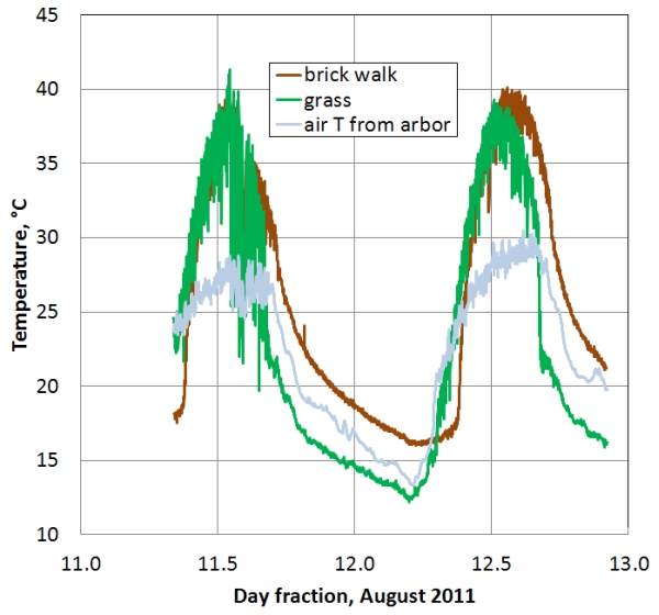
Returning to the matter of surface radiating temperatures, these devices can be used to investigate and understand the thermal properties of different kinds of surfaces. Such data have implications when studying heat islands and other differences between urban and rural areas. Concrete or asphalt surfaces respond much differently to diurnally varying solar insolation than vegetated surfaces. It is not just the additional heat sources in urban areas that produce heat island effects, but also how different surfaces respond to solar radiation by storing and releasing thermal energy at different rates. The graph shows some data collected over a brick walk (the same site used for the thermopile comparisons described above) and a grassy surface, compared with air temperature at a site at the edge of the grassy surface. The grassy surface is at the side of our house and the brick walk is in back of the house, "downhill" about two meters lower than the grassy site and with a different sun exposure. These two surfaces reach roughly the same maximum temperature during the day. The thermal inertia of the brick walk causes temperature changes to lag behind the changes in air temperature and the temperature stays well above the ambient air temperature until the next morning. The timing of temperature changes over the grassy surface more closely track changes in air temperature in the morning, but the surface cools quickly at night and the temperature falls below the air temperature. This brief experiment provides some useful insight into the behavior of different kinds of surfaces. It can be assumed that soil moisture content, winds, and sky conditions at night are factors that are also important for understanding these differences. |
 |
These sensors are not intended to be exposed to direct sunlight or moisture. Therefore, they should always be pointed down toward the ground and protected from rain. It might be worthwhile to place the sensor package under a small inverted saucer to keep water from dripping on the instrument.
Be careful when you handle this instrument and avoid touching the window. Oil from your fingers and dust or dirt may change the calibration of the sensor.
As supplied, the instrument has a 9-V battery clip but no on/off switch. The instrument will stop operating if the battery voltage drops below 7 V. The 9-V battery supplied with the kit is intended primarily for testing purposes and will last no more than a couple of days in continuous operation. A high-quality alkaline battery will last for several days in continuous operation. For long-term operation, other power supply options should be considered. 6 D cells connected in series is one option. A 12-V lead acid battery is another option. Such a battery could be kept charged with a small 12-V solar panel with a charge controller. If AC power is available, just about any 9- or 12-V "wall wart" supply should work.