Electricity Fundamentals for Using Arduinos

      Arduino microcontrollers are extremely useful devices for controlling hardware, but you must understand some basic electricity fundamentals to use them properly. The fundamental principle is that when you use digital and analog pins to respond to input or provide outgoing signals to control or power external devices, you must be careful not to exceed your Arduino's capabilities. This discussion assumes you are using an Arduino Uno R3 board, which is the most widely used Arduino.
      Let's start with the requirements for providing an input signal to an Arduinio "analog" pin – one of 6 pins to which an external voltage can be applied. These signals are typically associated with output from an external sensor which you are asking your Arduino to read and interpret. The requirement for such a signal is that the voltage input must be between 0 and +5 V. Negative voltages and voltages above +5 V aren't allowed. If you don't follow this requirement, you may destroy the pin to which the inappropriate voltage is sent and you may also destroy your entire Arduino board. Voltages outside the 0 to +5 V range should never be applied to any Arduino pin under any circumstances.
      You must also understand the requirements for using Arduino's "digital" pins, which can be operated as either "output" or "input." When they are set as output pins they are used to provide power to some external device, and this is where you need to be careful. Arduino boards can provide only a limited amount of power because they are, after all, physically very small devices! First, consider some electricity fundamentals. Electrical power P (watts) is given by the product of the current I (amps) times the voltage V (volts).

P = I•V

      The voltage available at an output pin is fixed at +5 V. When you attach a device to the pin, current will flow between the pin and ground, assuming the "other end" of the device is attached to ground. The amount of current is determined by the resistance provided by the device, measured in ohms (Ω). Current I, voltage V, and resistance R are related through the fundamental equation of electrical circuits, Ohm's Law:

V = I•R

      Here is a schematic representation of the circuit for a device attached to an Arduino output pin. Suppose the resistance R is 500 Ω. Then the current flowing from the pin to ground is 5/500 = 0.010 A or 10 mA. Is this good or bad?
      For Arduino Uno boards, the absolute maximum current that should be drawn from any pin for even a brief time is 40 mA. In fact, you should always keep the current well below this value. For a steady current being drawn continuously from a pin, you should limit the value to no more than 20 mA. Based on these values, a device providing a resistance of 500 Ω is perfectly safe.
      There is an additional requirement that the total current drawn from all pins should not exceed 200 mA. For the previous example, this means that you could power several such devices from multiple pins.
      To look at it another way, no Arduino pin should be asked to provide more than

P = I•V = 5•0.020 = 0.1 watt

and the total power drawn from all pins should be no more than 0.2 A or

P = I• = 5•0.20 = 1.0 watt

      Whenever you connect any device to an Arduino pin, you should make sure the current and total power will not exceed the allowed limits. For "active" devices which require power to operate, you must look at a datasheet to determine their power requirements, assuming that they can be powered from +5 V. For passive devices, you may need to include a "current limiting resistor."
      First, let's look at a typical "active" device that can be powered from an Arduino pin. The TMP36 is a temperature sensor which provides a voltage output that is linearly proportional to its temperature. The datasheet for this device states that "The supply current runs well below 50 μA..." Thus this device places hardly any power requirements on your Arduino.
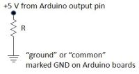
      Now, let's look at a typical introductory Arduino project: powering a light emitting diode (LED). Assuming you don't know ahead of time how LEDs behave, and just on general principles, you should include a current limiting resistor in the circuit to protect your Arduino. 
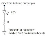
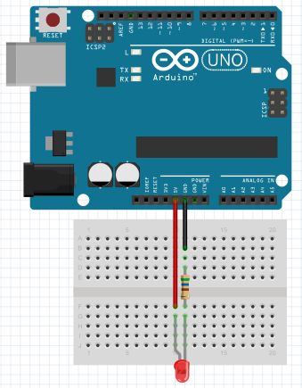
For this example, the positive lead of a red LED (always the longer lead) is connected through a 560 Ω resistor to ground. (Note that no code is required for this demonstration. All that is necessary is to apply power to the Arduino board.) What is the current flowing through this circuit?
      A fundamental circuit principle is that when several devices are connected "in series," as these are, the current through all the devices must be the same. What you need to know is how the voltage from the power source (+5 V) is distributed between (or among) the devices connected between the power supply and ground. The unique characteristic of LEDs is that they have a built-in voltage drop (also called a "forward voltage"), which depends on the color of the LED, as determined by the chemical compounds used to make the LED chip.
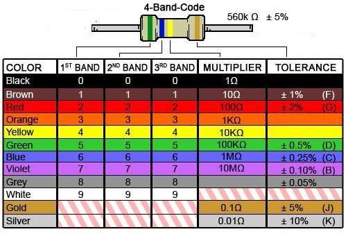
      The table below shows forward voltages for various LEDs. Red LEDs have typical forward voltage drops of 2.0 V. For the red LED used in this circuit, when power is applied to the board the voltage across the resistor is 3.15 V, which means that the voltage drop across the LED must be 1.85 V, within the range of values tabulated below. This means that the current flowing through the resistor (and also through the LED) is

I = V/R = 3.15/560 = 5.6 mA.

It is possible to measure this current directly, but it is not necessary because Ohm's Law guarantees the result.
      For this circuit, the total power being provided by the Arduino is the total voltage drop times the current:

P = I•V = 5.6•5 = 0.028 watts.

The power consumed by the resistor is 5.6•3.15 = 0.018 watts. This value is important in principle because resistors are rated for a maximum power consumption. The carbon film resistors typically used for these kinds of circuits are rated at 1/2, 1/4, or even 1/8 watt – far from being a problem for these circuits.
     

LED color
(set by the chemistry of the LED chip)
voltage drop across LED
(forward voltage)
green (InGaN)3.0-3.5, 3.2 typical
blue (InGaN)2.8-3.5, 3.2 typical
red, orange (amber), yellow, green (GaP)1.7-2.4, 2.0 typical

     
      There is one other factor to consider when using Arduinos to power devices. For the simple LED project above, power was supplied not from one of the input/output (I/O) pins, but directly from the +5 V power pin. This pin draws power directly from the power source rather than from the onboard voltage regulator that powers the I/O pins. This pin will supply ~400-500 mA under USB power from your laptop or desktop computer and ~900 mA when an external power adapter is used, as long as that power adapter is rated to supply that much current at its rated voltage. (Such power supplies must provide at least +7 V to the board, but no more than +12 V.)
      There is also +3.3 V power pin which can supply up to 150 mA. (Some devices you might wish to use with an Arduino require a +3.3 V power supply rather than +5 V.) The current drawn from this pin must be included in the total current drawn through all devices powered from both the +5 V and +3.3 V pins.
     
      As a final point, it is worth noting that are a limited number of carbon film resistance values which are commonly available. The values which would be used as current limiting resistors on Arduino pins include:

220, 240, 270, 300, 330, 360, 390, 430, 470, 510, 560, 620, 680, 750, 820, 910, 1000 Ω

Why these particular values? I don't know, except to note that each resistance value in this series is very roughly 10% higher than the previous one.
      The value of a carbon film resistor can always be determined from its (standardized) four-band color code. The first three bands give the resistance value and the fourth band gives the tolerance, which is almost always gold, or 5%. here is a color code chart.